7900GT VOLT MOD - 7900GT OVERCLOCK -7900GT CORE MEMROY
![]()
|
|
 |
||||||||||||
| Posted:2006-04-10 By hardware review Number of View:18788 |
|||||||||||||
By :hardware review Posted:2006-04-10
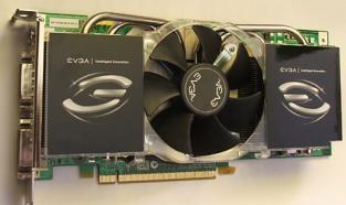
7900gt volt modI received my7900GTyesterday, and could do quite some testing to solve some problems that where still there. 7900gt volt modAll the necessary mods are combined in the next mail, because I did not manage to get everything in this mail! 7900gt volt mod
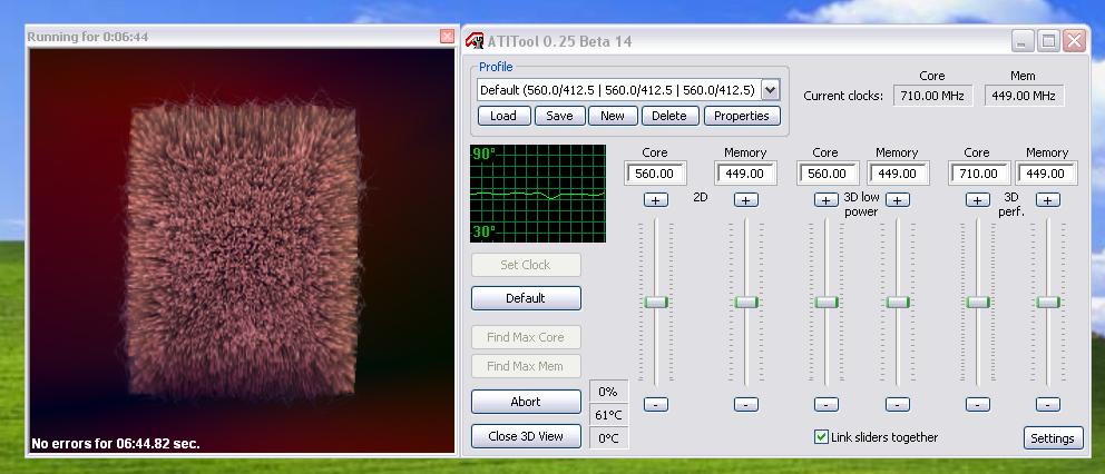
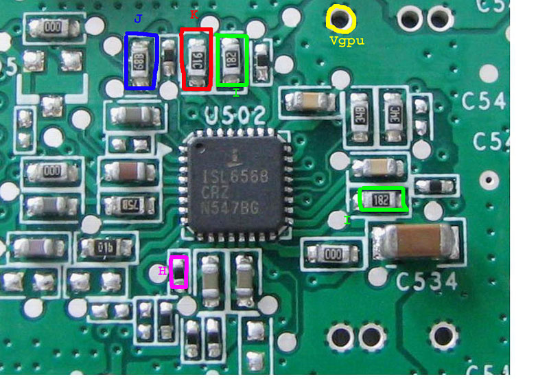
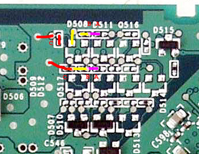
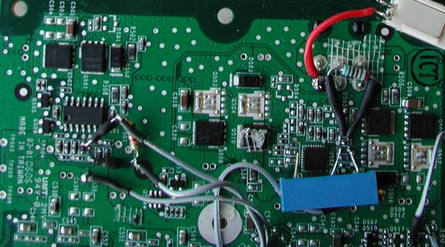
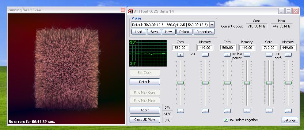
Resistor "J" is a 5Kohm resistor, and causes the Core Voltage, Vgpu, to be 1.2Volt in the unmodified situation. 7900gt volt modI have given two possible routes to achieve your Vgpu increase. A bit messy, but here are the vmods i did 7900gt volt moda quite good result for quite good d job 710Mhz Core and 1800Mhz Mem u can check here the 7900 gt super clock review or here for the 7900gtx super clocked review
we would be happy to answer for your question . if you have suggestion or comment
regarding this review our support would be glad to help just join our forum and ask u will get the best answer
to discuss check our forum section :-) RATE THIS REVIEW | |||||||||||||
![]()

7900gt volt mod - 7900gt overclock -7900gt core memroy
7900gt volt mod - 7900gt overclock -7900gt core memroy


7600gt review
7600gt is the middle card range.
We already benchmarked this video card and found that ...

 geforce 8800gtx and 8800gts
  Xtreview software download Section
  AMD TURION 64 X2 REVIEW
  INTEL PENTIUM D 920 , INTEL PENTIUM D 930
  6800XT REVIEW
  computer hardware REVIEW
  INTEL CONROE CORE DUO 2 REVIEW VS AMD AM2
  INTEL PENTIUM D 805 INTEL D805
  Free desktop wallpaper
  online fighting game
  Xtreview price comparison center

- The new version of GPU-Z finally kills the belief in the miracle of Vega transformation
- The motherboard manufacturer confirms the characteristics of the processors Coffee Lake
- We are looking for copper coolers on NVIDIA Volta computing accelerators
- Unofficially about Intels plans to release 300-series chipset
- The Japanese representation of AMD offered monetary compensation to the first buyers of Ryzen Threadripper
- This year will not be released more than 45 million motherboards
- TSMC denies the presentation of charges from the antimonopoly authorities
- Radeon RX Vega 64 at frequencies 1802-1000 MHz updated the record GPUPI 1B
- AMD itself would like to believe that mobile processors Ryzen have already been released
- AMD Vega 20 will find application in accelerating computations
- Pre-orders for new iPhone start next week
- Radeon RX Vega 57, 58 and 59: the wonders of transformation
- ASML starts commercial delivery of EUV-scanners
- The older Skylake processors with a free multiplier are removed from production
- Meizu will release Android-smartphone based on Helio P40
- AMD Bristol Ridge processors are also available in American retail
- The fate of Toshiba Memory can be solved to the next environment
- duo GeForce GTX 1080 Ti in GPUPI 1B at frequencies of 2480-10320 MHz
- New Kentsfield overclocking record up to 5204 MHz
- Lenovo released Android-smartphone K8


computer news computer parts review Old Forum Downloads New Forum Login Join Articles terms Hardware blog Sitemap Get Freebies

